meta data for this page
Eufhemism
Group members
| Name | Student number |
|---|---|
| Darren Andrew | 0528679 |
| Mansour Kheffache | 0528776 |
| Sami Kabir | 0528747 |
| Vesa Ylämäki | 0507933 |
pysäköid.ai
Vision
We envision an autonomous parking facility for vehicle, where all processes required for daily operations are fully automated without the need for human assistance, while having a low carbon footprint.
Components
- Parking Slot Allocation
Once a car enters into the parking area, the display board will show the driver nearest vacant parking slot number. Afterwards, this board will guide the user to reach that parking slot by showing him the direction and distance.
- Energy-Based Payment
The car will transfer its electrical energy to the central electrical reservoir of the parking area in exchange for parking payment fee.
- Adaptive HVAC + Lighting
Heating, Ventilation, and Air Conditioning and Lighting will be turned on or off automatically based on the sensor response.
- Automated Cleaning and Waste Disposal
Image sensors will detect waste objects' presence on the parking floor and communicate the object location to the automated vacuum cleaner. This cleaner will move to that location, clean that waste and return to its original position.
- Automatic Fault Detection
In case a sensor or a light or any other electronic device becomes dysfunctional, this message will automatically be communicated to the authority by an automated messaging system.
Technology
On the surface:
Drive-in
Allocate parking spot
Get directions
Plug car to micro-grid
Do “stuff”
Come back to car, and leave
Behind the Scenes:
Fleet management
HVAC + Lighting adapt to utilization
Draws energy from cars depending on time
Automatically decides areas to clean
Report a fault in case of malfunction
Architecture
Sustainability
- Less fuel/electrical energy wasted looking for a parking spot
- No energy wasted in energy transport from local power plant to facility
- Replaces the human
Protocol
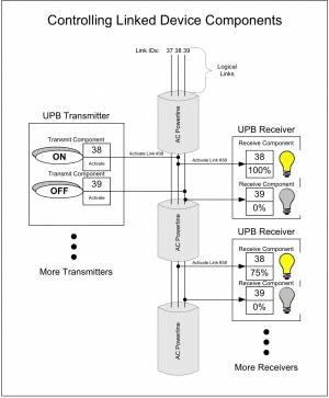
UPB - Universal Powerline Bus
- for communication among devices
- uses powerline wiring for signaling and control
- developed by PCS (Powerline Control Systems, Northridge CA)
- released 1999
- based on concept of X10 standard
- inproved transmission rate
- higher reliability > 99 % (X10 70-80 %)
Physical communication method
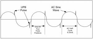
Digitally encoded information is sent over the electrical powerline as a series of precisely timed pulses. The pulses are superimposed on top of the AC sine wave.
Fig. 1 UPB Pulse
Pulses are generated by charging a capacitor in the transmitter and then discharging it. A pulse can be sent once on each half-cycle. One pulse transmits two bits of information. Pulse value is selected by timing the pulse on one of four predefined positions. Transmitter tolerance for timing is ±40 μs.
Fig. 2 UPB Timing
UPB works on single-phase, split-phase and 3-phase powerlines.
Data communications
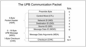
The UPB Byte forms of four pulses (8 bits).
Fig. 3 The standard UPB Communication Packet
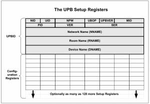
The first byte of the packet is called a preamble byte and it is used for synchronization on the receiver device. Preamble byte is always form of 2-1-1-2. The packet header contains information about the packet size, source, destination etc.
Fig. 4 The Packet Header
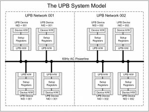
The UPB System model
If we had more time
Only having a few day to work on the project was not ideal and we only had a chance to implement a few ideas. There was a few more sensors and logic we would of liked to implement into the prototype if we had more time.
Table- with things we wanted to do.
Poster
Documents
Final report: Final presentation:pysaekoeid_presentation.pdf Link to code: code.zip

